The Nature of Monophonic Sound
In the beginning, all audio recordings were monophonic, though nobody described them as that or cared, because there was no alternative. When recordings were made, the sound was captured by a single horn, and when played back acoustically it came out of a similar horn. Later, electrical recording used a microphone (occasionally several) and a single loudspeaker, and the reproduced sound that was heard still came from a single point source.
Acoustic Recording
The early recordings, designed by Thomas Edison, were engraved with a stylus on cylinders. The audio waveform was represented by cutting more or less deeply into a groove on the surface of the cylinder as it rotated. This is called hill and dale recording. When discs, designed by Emile Berliner, became the preferred medium (because they were more easily manufactured) the decision was taken to record the waveform in the form of side to side movement within the groove. This method remains in use for mono recordings on vinyl, the option of hill and dale having been abandoned, probably because of the effects of gravity.
The Invention of Stereo
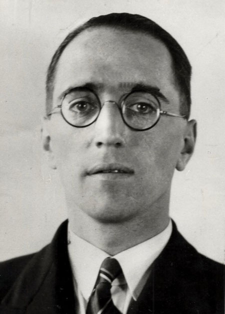
Alan D. Blumlein (1903 – 1942)
Around 1930, stereo was invented independently by Bell Labs in the USA and by Alan D. Blumlein at EMI Labs in England. The systems were different. The Bell system used two or more spaced microphones to capture the sound and feed it to two or more loudspeakers. Blumlein’s method used two microphones and two loudspeakers. At first the two microphones had omnidirectional polar diagrams and were close together in the horizontal plane, but this necessitated complicated electronic manipulation of the outputs to produce the left and right signals. The method that Blumlein then developed was to use a microphone with two metal ribbons angled at 90 degrees to each other in a magnetic field, with the fronts of the microphones facing 45 degrees to left and right respectively. The voltages induced in the two ribbons as they moved under the influence of the acoustic sources had figure of eight polar diagrams which between them covered sources from all around. The photo below shows one of these experimental stereo microphones. It is very large and cumbersome because of the need to generate a strong magnetic field around the ribbons by means of dc powered electro-magnets. In actual use it would have been suspended in the air on ropes or wires passing through the three rubber mounts at the top. Modern stereo ribbon microphones using the same principles employ much smaller and more powerful permanent magnets and place the left and right ribbons above each other.
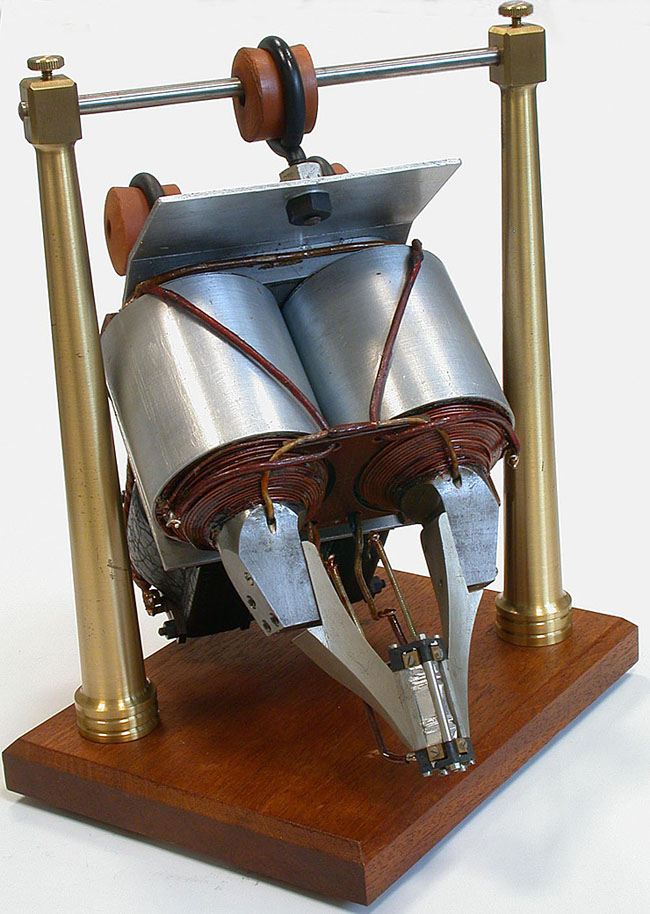
Blumlein’s experimental stereo ribbon microphone
Sum and Difference Components
In developing his system, Blumlein developed a theory of stereo which is still useful today, even though we often use more than two microphones for recording. He realised that if one were to put the left and right signals on the two sides of a groove with walls at 90° to each other, the signals would not interfere with each other and could be read by a single electro-mechanical pickup, amplified and sent to the left and right loudspeakers without further manipulation. He also realised that the vertical motion of the stylus (the original hill and dale recording method) pointed to a different way of analysing and manipulating a stereo signal.
Blumlein’s approach was to add the signals on the left and right hand groove walls, which would cancel out the vertical (hill and dale) motion, leaving only the lateral movement. He called this the Sum signal. He also subtracted the signal on the right hand groove wall from that on the left hand wall, thus cancelling out the lateral movement, and providing a representation of the vertical movement of the stylus – the Difference signal. It doesn’t take much of a step to realise that the lateral movement is a mono signal, familiar from the monophonic recording described earlier. It is the signal common to both left and right channels and can be played back on its own. This has implications for the compatibility of stereo. Blumlein also realised that the difference signal (also mono) represents the stereo information. He further realised that a stereo signal can be completely represented by either the left and right signals or the sum and difference signals – though only the former can be used to feed the two loudspeakers directly – and that varying the balance of sum and difference changes the width of the stereo signal between the two loudspeakers.
Conversion between Left/Right and Sum/Difference
If the two parts of a left/right stereo signal are represented by L and R, the sum and difference components (S and D) may be defined as (L + R) and (L - R). As described above, these represent the lateral and vertical modulations on a stereo analogue disc and their electrical representation can easily be added and subtracted:
S = L + R
D = L - R
If we add the sum and difference components we have:
S + D = (L + R) + (L - R) = 2L
Similarly,
S - D = (L + R) - (L - R) = 2R
and we end up with left and right, but twice the amplitude.
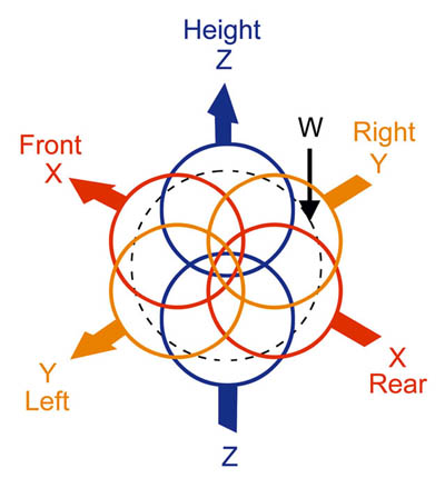
In order to avoid this unwanted doubling of amplitude we use a factor of 1/√2 in each of the above equations, since 1/√2 x 1/√2 = 1/2, and we can transform from left and right to sum and difference and back again without any change. If the L and R signals are treated as vectors pointing +/-45° to the centre line of the microphone pair, 1/√2, which is the value of both sin(45°) and cos(45°) is automatically part of the equations. It follows that a pair of figure of eight microphones pointing to the front and the left hand side respectively will make a stereo recording in sum and difference which can readily be converted to L & R. This configuration is actually often chosen because of its symmetry, which conserves a balance of signals between the left and right channels.
Comparison of L & R and S & D
We can now understand how a mono source in the stereo , either placed by panpot or representing the position of a narrow source captured by a stereo pair of microphones, is represented either by the left and right signals or in terms of the sum and difference signals.
Table I
| | L | R | S | D |
|---|
| Centre in phase |
0.707 | 0.707 | 1.0 | 0.0 |
| Centre out of phase |
0.707 | 0.707 | 0.0 | 1.0 |
| Left only |
1.0 | 0.0 | 0.707 | 0.707 |
| Right only |
0.0 | 1.0 | 0.707 | -0.707 |
We see in Table I that equal in phase L & R signals have only a sum (or, in terms of an analogue disc, lateral) component, and that equal out of phase L & R signals have only a difference (or vertical) component. Sources present in only one channel have equal magnitude components in both the sum and difference channels, and the equations preserve the distinction between the left and right channels by assigning negative polarity to the difference channel.
The Panpot Law
A panpot is used in recording mixing consoles and DAWs to position a monophonic source in the stereo sound field. It has a voltage law which is ideally a sine function in the right hand channel and a cosine function in the left hand channel. For a mono source moving from left to right the panpot sends the input signal multiplied by the cosine of the angle travelled (i.e. a full traverse of the soundstage from hard left to hard right uses the cosine shape from 0° to 90°) to the left hand channel and the sine of the angle travelled (also from 0° to 90°) to the right hand channel.
These shapes have been chosen in order to keep the total power from the two channels constant (sin2 θ + cos2 θ = 1), and therefore to prevent the loudness of the source to appear to change as it is moved across the sound stage. At all positions of the panpot, the sum total of the power sent to the two channels is constant, and thus the source does not appear to move closer to or further from the listener. Table II demonstrates this and gives the correspondence between apparent angular displacement of a mono source from the centre line and the relative level of the left and right signals in decibels (centre column). The first column assumes loudspeakers at +/-45° degrees to the centre line, while the third column is for the more normal practical situation of loudspeakers which are at +/- 30°.
The first row represents the source in the centre of the soundstage, with equal left and right signals. As the source is moved towards the left, the magnitude of L/R increases, and moving to the right increases the magnitude of R/L. If we examine the row that represents half left or half right (22.5° from the centre for speakers at +/-45° or 15° for speakers at +/-30°), we see that L/R or R/L is 7.7dB. Looking at the last row, we note that the source is coming from a position very close to the centre of the loudspeaker with an L/R or R/L ratio of only 27.2dB. Further increase in the ratio – until ∞ dB – brings the source entirely within the loudspeaker, and it can readily be understood that the effect of values between 30dB and ∞ dB differs very little.
Table II
angle from centre
(LS +/-45°) | R/L or L/R (dB)
| angle from centre
(LS +/-30°) |
|---|
| 0.0° | 0.0 dB | 0.0° |
| 2.5° | 0.8 dB | 1.7° |
| 5.0° | 1.5 dB | 3.3° |
| 7.5° | 2.3 dB | 5.0° |
| 10.0° | 3.1 dB | 6.7° |
| 12.5° | 3.9 dB | 8.3° |
| 15.0° | 4.8 dB | 10.0° |
| 17.5° | 5.7 dB | 11.7° |
| 20.0° | 6.6 dB | 13.3° |
| 22.5° | 7.7 dB | 15.0° |
| 25.0° | 8.8 dB | 16.7° |
| 27.5° | 10.0 dB | 18.3° |
| 30.0° | 11.4 dB | 20.0° |
| 32.5° | 13.1 dB | 21.7° |
| 35.0° | 15.1 dB | 23.3° |
| 37.5° | 17.6 dB | 25.0° |
| 40.0° | 21.2 dB | 26.7° |
| 42.5° | 27.2 dB | 28.3° |
(Note: The large amounts of data in the above table and in Table IV below have been included in order that users of DAWs that have controls calibrated in decibels can look up the needed values from the required angles.)
Table III below (which is an extension of Table I) shows another representation of what happens to the sum and difference components as a mono source is panned across the sound stage, while the overall acoustic level is kept constant, and will reinforce the statements above. (It has been assumed that the loudspeakers are at +/-45°.)
Table III
| POSITION | L | R | S | D |
|---|
| Hard left (45° L) | 1.0 | 0.0 | 0.707 | 0.707 |
| Half left (22.5° L) | 0.924 | 0.383 | 0.924 | 0.383 |
| Centre (0°) | 0.707 | 0.707 | 1.0 | 0.0 |
| Half right (22.5° R) | 0.383 | 0.924 | 0.924 | -0.383 |
| Hard right (45° R) | 0.0 | 1.0 | 0.707 | -0.707 |
This table may look a little strange at first, but a close examination reveals that, if the values are understood as voltages representing the magnitude and sign of the signal, the normal cosine/sine law of the panpot is respected. As explained earlier, this law was chosen because the total power from the two channels is kept constant (sin2 θ + cos2 θ = 1), and therefore the source will not appear to change in level as it is moved across the sound stage. Squaring the voltages, we can see that in each row the total power in the left and right columns, L + R, is constant, as also is the total power in the sum and difference columns, S + D. Intermediate positions could also have been added to the table, but the five positions given will be adequate to demonstrate the mechanism of the panpot and allow some useful additional observations.
In this table, since we are representing only the possibility of panning a mono source between the two channels, the sum signal is always greater than 0.707, and the difference signal takes positive or negative values to represent left or right biased sources respectively. However, because the source is never moved further out than either of the two loudspeakers, the magnitude of the difference channel is never greater than that of the sum signal. Using a simple panpot it is impossible to move the source any further out than this. However, in coincident stereo pair recording (using, for instance, two figure of eight microphones) it is quite possible for sources to emanate from a point beyond the two loudspeakers. In multi-mic recording, therefore, another method of varying the level of the sum and difference signals must be sought to allow us to move the position of a source out beyond the speakers.
Spreading and De-spreading
Some recording consoles and DAWs have a control that spreads or de-spreads the stereo signal – called, believe it or not, a spreader. Spreader circuits were already part of Blumlein’s arsenal. By changing the balance of sum and difference this control spreads (broadens) the stereo image by moving the L & R extremes closer to the loudspeakers, or de-spreads (narrows) it by collapsing the image towards the centre. Used with a single mono source that is not central the same control can be used to move the source towards or away from the loudspeaker.
Table IV below gives the amount by which the difference channel has been changed using a spreading control, the sum channel being left unaltered. For the purpose of illustration this represents a 12-position switch, which has no effect in the central position. Moved to the left (or anti-clockwise) reduces the difference signal by 2dB per step, whereas moving it to the right (or clockwise) increases it by the same amount. Under each value for the spread is given the angular displacement of a source from the centre point. It is assumed that +/-45° represents the placement of the loudspeakers, but the figures will be in proportion with loudspeakers at +/-30°.
To see the effect of the spreader, find the initial position of the source in the central (light blue) column. Then move to left or right to find the desired position. The column in which this figure is found will indicate the number of clicks, or change to be made in the difference channel.
Table IV
| -10dB | -8dB | -6dB | -4dB | -2dB | 0dB | +2dB | +4dB | +6dB | +8dB | +10dB |
|---|
| 0.0° | 0.0° | 0.0° | 0.0° | 0.0° | 0.0° | 0.0° | 0.0° | 0.0° | 0.0° | 0.0° |
| 0.8° | 1.0° | 1.3° | 1.6° | 2.0° | 2.5° | 3.1° | 4.0° | 5.0° | 6.3° | 7.9° |
| 1.6° | 2.0° | 2.5° | 3.2° | 4.0° | 5.0° | 6.3° | 7.9° | 9.9° | 12.4° | 15.5° |
| 2.4° | 3.0° | 3.8° | 4.7° | 6.0° | 7.5° | 9.4° | 11.8° | 14.7° | 18.3° | 22.6° |
| 3.2° | 4.0° | 5.1° | 6.3° | 8.0° | 10.0° | 12.5° | 15.6° | 19.4° | 23.9° | 29.1° |
| 4.0° | 5.0° | 6.3° | 8.0° | 10.0° | 12.5° | 15.6° | 19.4° | 23.9° | 29.1° | 35.0° |
| 4.8° | 6.1° | 7.6° | 9.6° | 12.0° | 15.0° | 18.6° | 23.0° | 28.1° | 33.9° | 40.3° |
| 5.7° | 7.2° | 9.0° | 11.3° | 14.1° | 17.5° | 21.6° | 26.6° | 32.2° | 38.4° | 44.9° |
| 6.6° | 8.2° | 10.3° | 12.9° | 16.1° | 20.0° | 24.6° | 30.0° | 36.0° | 42.4° | 49.0° |
| 7.5° | 9.4° | 11.7° | 14.6° | 18.2° | 22.5° | 27.5° | 33.3° | 39.6° | 46.1° | 52.6° |
| 8.4° | 10.5° | 13.2° | 16.4° | 20.3° | 25.0° | 30.4° | 36.5° | 42.9° | 49.5° | 55.9° |
| 9.3° | 11.7° | 14.6° | 18.2° | 22.5° | 27.5° | 33.2° | 39.5° | 46.1° | 52.6° | 58.7° |
| 10.3° | 12.9° | 16.1° | 20.0° | 24.6° | 30.0° | 36.0° | 42.5° | 49.0° | 55.4° | 61.3° |
| 11.4° | 14.2° | 17.7° | 21.9° | 26.8° | 32.5° | 38.7° | 45.3° | 51.8° | 58.0° | 63.6° |
| 12.5° | 15.6° | 19.3° | 23.8° | 29.1° | 35.0° | 41.4° | 48.0° | 54.4° | 60.4° | 65.7° |
| 13.6° | 17.0° | 21.0° | 25.8° | 31.4° | 37.5° | 44.0° | 50.6° | 56.8° | 62.6° | 67.6° |
| 14.9° | 18.5° | 22.8° | 27.9° | 33.7° | 40.0° | 46.6° | 53.1° | 59.2° | 64.6° | 69.4° |
| 16.2° | 20.0° | 24.7° | 30.0° | 36.0° | 42.5° | 49.1° | 55.4° | 61.3° | 66.5° | 71.0° |
| 17.5° | 21.7° | 26.6° | 32.3° | 38.5° | 45.0° | 51.5° | 57.7° | 63.4° | 68.3° | 72.5° |
| 19.0° | 23.5° | 28.7° | 34.6° | 40.9° | 47.5° | 54.0° | 60.0° | 65.3° | 70.0° | 73.8° |
| 20.6° | 25.4° | 30.8° | 36.9° | 43.4° | 50.0° | 56.3° | 62.1° | 67.2° | 71.5° | 75.1° |
| 22.4° | 27.4° | 33.2° | 39.4° | 46.0° | 52.5° | 58.6° | 64.2° | 69.0° | 73.0° | 76.4° |
| 24.3° | 29.6° | 35.6° | 42.0° | 48.6° | 55.0° | 60.9° | 66.2° | 70.7° | 74.4° | 77.5° |
| 26.4° | 32.0° | 38.2° | 44.7° | 51.3° | 57.5° | 63.2° | 68.1° | 72.3° | 75.8° | 78.6° |
| 28.7° | 34.6° | 41.0° | 47.5° | 54.0° | 60.0° | 65.4° | 70.0° | 73.9° | 77.1° | 79.7° |
| 31.3° | 37.4° | 43.9° | 50.5° | 56.8° | 62.5° | 67.5° | 71.8° | 75.4° | 78.3° | 80.7° |
| 34.1° | 40.5° | 47.1° | 53.5° | 59.6° | 65.0° | 69.7° | 73.6° | 76.8° | 79.5° | 81.6° |
| 37.4° | 43.9° | 50.4° | 56.7° | 62.5° | 67.5° | 71.8° | 75.4° | 78.3° | 80.6° | 82.5° |
| 41.0° | 47.6° | 54.0° | 60.0° | 65.4° | 70.0° | 73.9° | 77.1° | 79.7° | 81.8° | 83.4° |
| 45.1° | 51.6° | 57.8° | 63.4° | 68.4° | 72.5° | 75.9° | 78.7° | 81.0° | 82.8° | 84.3° |
| 49.7° | 56.1° | 61.9° | 67.0° | 71.4° | 75.0° | 78.0° | 80.4° | 82.4° | 83.9° | 85.2° |
| 55.0° | 60.9° | 66.1° | 70.6° | 74.4° | 77.5° | 80.0° | 82.0° | 83.7° | 85.0° | 86.0° |
| 60.9° | 66.1° | 70.6° | 74.4° | 77.5° | 80.0° | 82.0° | 83.7° | 84.9° | 86.0° | 86.8° |
| 67.4° | 71.7° | 75.3° | 78.2° | 80.6° | 82.5° | 84.0° | 85.3° | 86.2° | 87.0° | 87.6° |
| 74.5° | 77.6° | 80.1° | 82.1° | 83.7° | 85.0° | 86.0° | 86.8° | 87.5° | 88.0° | 88.4° |
| 82.1° | 83.7° | 85.0° | 86.0° | 86.9° | 87.5° | 88.0° | 88.4° | 88.7° | 89.0° | 89.2° |
| 90.0° | 90.0° | 90.0° | 90.0° | 90.0° | 90.0° | 90.0° | 90.0° | 90.0° | 90.0° | 90.0° |
The Uses of a Spreader
A spreader like the one in Table IV can be used to widen or narrow the stereo image of a recording. It is rare that more than two or three clockwise or anticlockwise clicks are needed. At the same time it is often necessary to centre the image, and this is often most easily done by temporarily applying maximum spread and then adjusting the levels of L & R at a point in the system before they enter the spreader, such that what should be in the centre of the soundstage is actually so positioned. Then the final setting of the spreader is adjusted until the extremes of the soundstage are positioned as needed between the speakers. Sometimes an edit between two takes does not work because the spread, and perhaps also the L/R balance, are different in the two takes. These problems can be fixed as described above on one or other of the takes, which can then be joined successfully.